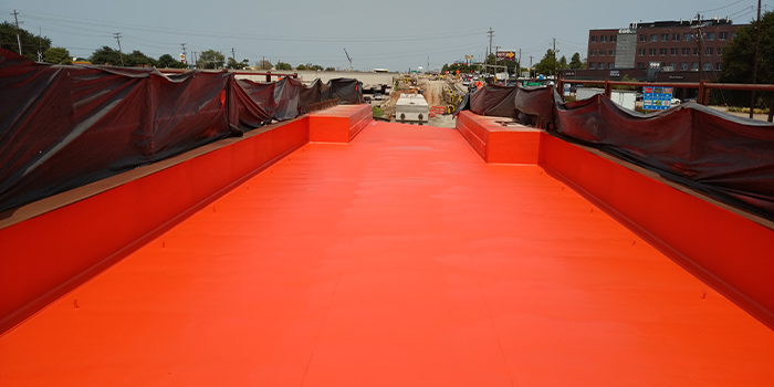
Transitioning from Spray Foam to Polyurea Spray

Spray Foam Magazine – In a previous article, information was discussed on what it takes to be successful in the fast set polyurea spray coating and lining business. But more than not, questions are always then asked if one can use the same equipment in spray foam work for polyurea applications? Great question as there is a vast array of equipment available, which is “best” so to speak. So this is not a simple yes or no answer, as additional relevant information needs to be disclosed. But first and foremost, the Polyurea System supplier should be providing this information, not the equipment manufacturer.
So let’s start at the beginning, shall we? So the basic rule of thumb, one needs to “downsize” from the start to finish, not the opposite which is sometimes noted in spray foam work. Meaning having more flow output capability at the start, thus controlling output (reducing) at the end – spray gun.
Material Supply Pumps:
So this is what feeds the beast here. The proportioning units really don’t “suck” here, or should I better say draw material. There shall be positive feed, which can either be the common stick pumps, diaphragm pumps or even pressurized tanks / gravity feed. The most common of course are the stick and diaphragm pumps. Pressurized tanks, or even gravity feed is not that efficient with polyurea systems (viscosity issue) except in some very isolated cases.
A rule of thumb here in polyurea workings, the material supply pumps should be able to deliver 2X the material that the proportioner is dispensing. So with that, min output for the supply pump should be at about 4 gals/min continuous as published. Have seen some very nice field equipment trailer setups, but using the lower flow stick pumps (lower cost) and they can’t figure out why all the spray issues during winter, or cooler temperature months.
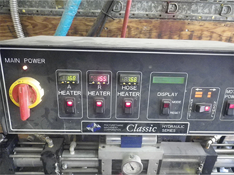
For large field type polyurea work, most will use a hydraulically driven pump due to overall performance and material supply.
Keep in mind that material outputs on the stick and diaphragm pumps is based upon mineral spirits (low viscosity) and not the material you are using. So actual continuous outputs will be less. And as the material in the drums gets colder, output drop even further. So it is very important that materials be conditioned properly and stored as per the system supplier, which is typically above 70°F (~25°C).
Proportioner:
As known, there are a variety of heated proportioning pumps on the market. These can be either electric, hydraulic or pneumatically driven. Each have their own characteristics and requirements. For large field type polyurea work, most will use a hydraulically driven pump due to overall performance and material supply. But whichever route is taken, it is important to understand what the maximum fluid output for the unit is, as well as the heating capacity.
The proportioning pump, contrary to what some may think, DOES NOT make pressure, it provides material flow. The “pressure” comes from how that flow is restricted in the process. When one increases the pressure, you are actually increasing the speed at which the pumps move. The faster they move, the more flow is generated.
The pressure generated comes from how that material flow is restricted, which can be from material viscosity, spray hose size, partial plugging of filter screens in the gun and orifice size in the spray gun. If the material is too cold, it will be higher in viscosity thus harder to pump – higher pressure results. So for polyurea systems, one needs to be able to heat and maintain the materials at a higher temperature than that used for spray foam. And keep in mind that for polyurea systems, the ISO side is generally higher in viscosity than the resin side (opposite of spray foam systems) so one may note a higher pressure on the ISO compared to resin during processing.
So it is not about how hot your machine will heat the material to, but how much the unit can heat the material to at the flow rates you are running at. This is where that terminology of delta-T comes into play. Polyurea systems are generally heated to min 140°F up to 160°F (60°C – 70°C), NOT for reactivity, but to lower the viscosity of the materials (as well as mix viscosity) to allow for the proper mix and atomization, or sprayability as we call it. So higher wattage heater units are typically required for polyurea systems.
And while not a subject of this writing, many of the newer proportioning units have flow meters attached. While not something new, in years past there were add-on flow meters systems that could be used. But this is great, right?? You’re on ratio now….. Ah but this is a false sense of security here, when do you check this? During the spray work or after the job is done, too late then. One can be “on ratio” as per volume flow, but be very much off mix, or even off ratio in the spray gun (no electric unit to measure that, but…). Having this type of “artificial intelligence” can adversely affect real learning in application work.
Spray Hose Assembly:
Hose Length & Size
200 feet, 3/8-inch
100 feet ½-inch / 100 feet 3/8-inch
300 feet 3/8-inch
100 feet ½-inch / 200 feet 3/8-inch
150 feet ½-inch / 150 feet 3/8-inch
400 feet 3/8-inch
100 feet ½-inch / 300 feet 3/8-inch
200 feet ½-inch / 200 feet 3/8-inch
Pressure Drop at Spray Gun
650 psi
470 psi
900 psi
730 psi
640 psi
1150 psi
990 psi
810 psi
In many cases, not much attention is paid to this part of the system. Spray hose is spray hose, right? Wrong! For polyurea systems, since material viscosities are much higher than normal spray foam system, heating capability and hose selection and size are extremely important, especially as one starts using 200+ feet of spray hose (more than 4 sections). It’s all about flow, and how that flow may be restricted, providing that pressure.
The issue of course here is pressure drop at the spray gun due to hose size and length. A presentation on this specific subject was done over 20 years ago, taking into account fluid flow Nomograph information.
So remember, the pressure gages are at the proportioner, not at the spray gun. The “assumption” has been made that all is good at the gun, when in fact there will be a significant pressure / flow drop. Not advocating using pressures gages at the gun mind you, just need to be aware of what is actually going on.
So take the following information for example and use it to your benefit. This represents a dynamic (spray) pressure of 2000 psi at the proportioning unit (with maximum 10-foot ¼-inch whip hose) at a flow rate of 1.5 gals/min (5.7 liters/min) with a polyurea system. This is the pressure drop at the spray gun, during spray application…
I bet you did not realize those drops, now some may understand why there were issues on some polyurea projects using long hose length…. So the moral of this is, use hose diameter downsizing as the hose length is extended on the spray unit. This is not just for polyurea, but this can also be applicable to spray foam work as well.
Spray Gun:
Ah yes, the million dollar question, which is the best spray gun for polyurea work? Of course this is where the “magic” occurs and the polyurea is actually made. So which is it, Air Purge or Mechanical Purge? When properly setup, they both work, so often times it becomes a preference by the applicator, or the specific equipment supplier. But one of the differences between spray polyurethane foam and polyurea spray systems, for polyurea the reaction starts immediately when the two materials mix in the chamber. This reaction builds viscosity, so material needs to enter the chamber, mix and then exit as quickly as possible. One has to “flood” the mix chamber, not restrict it for polyurea.
It has been shown many times that a properly setup mechanical purge gun provides for better mixing in a polyurea system over an air purge gun. Why? Well this goes back to when the polyurea technology was first developed, for Polyurea RIM (Reaction Injection Molding) work for automotive application.
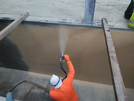
It has been shown many times that a properly setup mechanical purge gun provides for better mixing in a polyurea system over an air purge gun.
It relates to something related to the characteristic of flow and mixing called Reynolds Number, and numerous technical papers have been present over the years on this subject. A mechanical purge gun, with pattern tip, provides for some back-pressure in the mix chamber to finish out the mix. There is an air purge gun though that mimics this, more on that in a later article.
But most importantly with the spray gun, the output capacity of the spray gun should NOT exceed the output capacity of the proportioning unit. Need to size the gun to the capability of the proportioner, it’s all about flow… This is what should be restricting the material flow, not any of the previous parts of the processing system. For example, if the max output for your proportioner is 2 gals/min as published, don’t use a “5252” chamber for example, max should be a “4242” for example.
So one of my pet peeves is, why in the world would a plural component spray gun, with mix chamber orifices at over 0.029-inch in diameter be supplied with 80-mesh filter screens??? The “holes” in an 80-mesh screen are about 0.007 inches, whereas a 40-mesh screen has “holes” that are ~ 0.017 inch in size.
You are restricting flow with the 80-mesh screens (and filtering too much) before material gets to the proper restriction point of the orifice size in the mix chamber. One only needs to filter out any particles that are larger than the orifice size. Size your filter screens to the orifice size in the mix chamber, novel idea right??? And interestingly enough, one equipment supplier for airless spray guns actually has a chart and information for use of the proper filter screen size based upon the spray tip size being used. It further notes that by doing this one can significantly improve the surface qualities of the “paint.”
So bottom line here, one does not restrict flow using adjustments to the proportioning unit, flow is then restricted via the spray gun setup for successful polyurea work.
An Industrial Example:
So while taking all this information into account, a polyurea project in upper New York State was specified, with application during the winter. Average ambient temperature during the project was 28° F (-2° C). The challenge, the applicator for the project was limited with an E-20 proportioner as was also applying some spray foam system. While this setup would not normally be used or recommended in polyurea work, significant discussions were had between the applicator, material supplier and a highly experienced consultant / project manager.
While knowing the complete characteristics of the polyurea system specified; which included the chemistry and processing characteristics, a logical path forward was employed. The drums of material were kept in a heated warm room on project site, the spray hose was limited to 2-sections (100 feet and 10-foor whip) and a mechanical purge spray gun was used with a maximum output setup of about 0.5 gals/min.
Sure it was slower to complete the application due to restricted output in the spray gun, but the project was successfully completed. So things can be overcome, use your knowledge.
For use by SprayFoamMagazine.com & Spray Foam Magazine


